Laboratories and Research Facilities
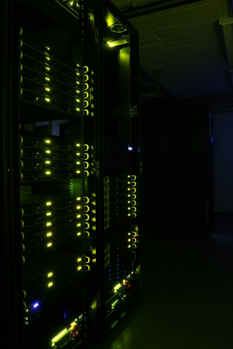
High Performancecomputing Cluster (HPC)
Data
Internal HPC-Cluster
University HPC-ClusterAmplitUDE
- Supplier: MEGWARE GmbH
- 240 CPU-Cores with each 2x Intel® Xeon® Platinum 8480+ Prozessor thereof
- 176 "Standard" (512 GB RAM)
- 51 "High-Mem" (1 TB RAM)
- 13 "Super High-Mem"(2 TB RAM)
- 19 GPU-Cores with each 2x Intel® Xeon® Platinum 8480+ Prozessor thereof
- 15 with 4x NVIDIA H100
- 4 with 2x NVIDIA H100
- Mellanox InfiniBand NDR200 with Blocking 1:1,66
- Lustre File-System with approx. 2,1 PB Capacity
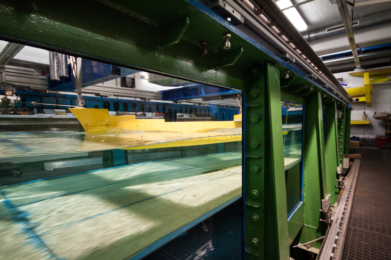
Water Tank
Water Tank F07
In the ship building industry, the use of model test stations is still common practise to evaluate the construction or re-construction of a ship and to optimize the hull geometry. Unlike in the car production sector, a set-up of a ship prototype is not cost-effective owing to the ship's enormous measurements.
Therefore, the specific parameters are taken off a ship’s model and its propeller true to scale, based on three central experimental test procedures. This, in particular, includes the ship’s resistance test which is of crucial importance for the installation of the appropriate propulsion as the built ship needs to meet contractual agreements such as a fixed duty velocity. The propeller’s characteristics are determined by the propeller open water test; the interaction between ship and propeller is assessed with the so-called propulsion test. More particularly, the values of thrust and torque are recorded.
The INAM is equipped with several test stations allowing insight into the model test station technique and the evaluation of ship and propeller geometry to the students. The data is mechanically recorded by the appropriate measurement scales; fluids' velocities are taken mechanically or by a laser-doppler anemometer. The water tank is also used in teaching. This traditional measurement technique is highly advantageous as supplementary effects such as additional resistance in shallow water are very vividly presentable.
Laboratory Manager: Dr.-Ing. Jens Neugebauer Data
Water Tank F07
| Range of measurement section: | 6x 1,5x 0,75 m |
| Variable water depth: | up to 0,7 m |
| Flow velocity: | max. 2 m/s |
| Model size: | 0,3 – 2 m |
Cavitation Tunnel
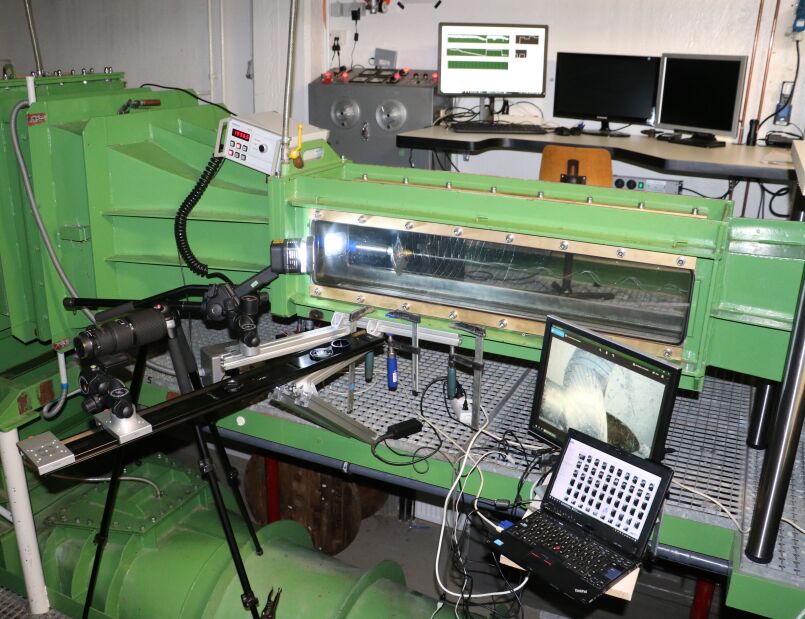
Laboratory Manager: Dr.-Ing. Jens Neugebauer Data
Cavitation Tank K23
| Range of measurement section: | 1,1 x 0,3 x 0,3 m |
| Flow velocity: | max. 9 m/s |
| Propeller diameter: | max. 0,15 m |
| Static pressure: | 0,1 - 2 bar (total) |
Cavitation Tunnel K23
Investigations which are conducted in the cavitation tunnel will ideally lead to an efficient draft of a ship. However, the power transmission by the propeller is connected to an undesirable physical phenomenon, the cavitation.
On both sides of the single propeller blades, the pressure could decrease in such the water’s vapor pressure is too low. Thus, the water starts vaporing at room temperature; this is called “pressure cavitation” or “suction side cavitation”, according to its occurrence.
Particularly, the collapsing of the vapor bubbles leads to a material abrasion off the propeller and the rudder, which is to be avoided under all circumstances. Due an experimental investigation in the cavitation tunnel, the common danger of cavitation and the area of its occurrence, could be determined.
The propeller open water test, i.e. the propeller’s characteristic in a homogenic flow towards the propeller, could also be determined in the cavitation tank. Thrust and torque are measured and the propeller efficiency is calculated. All measurements are summarized in a typical open water diagram.
The dynamometer reaches up to 5000 min-1 revolutions per minute (r.p.m.) and is capable to transfer and measure forces up to 500 N, and rotation moments up to 10 Nm. Measurements of force are taken by strain measurement gauges, difference pressure sensors take the flow towards the propeller, and an impulse counter detects the revolutions per minute.
The sensor technology has been recently renewed and fundamentally over-hauled. The measurement signals are recorded and processed by a measurement amplifier. Additionally, local speeds and velocity fields could be recorded via 2D Linear Method system (e.g. the propeller jet) and by Laser Doppler Anemometry.
Sloshing-Lab
Sloshing-Lab
At the Sloshing station, the ship’s motion is simulated with a fixed tank made of plastic representing the ship’s cargo tank. Owing to technical reasons, the cargo tanks are not completely filled with fluids in general. If the cargo fluid is induced to slosh around due to the tank’s motions, it is called Sloshing. To which degree the sloshing occurs depends on the tank’s motions and its frequency. At the station, usually the frequency rates are used that correspond to common waves. Even in moderate waves, sloshing could lead to high burdens onto the tanks. In the laboratory, the tank’s burdens are taken by metrological instruments and are evaluated.
Investigations regarding the burden on liquid gas tanks aboard a ship are conducted in the sloshing station. These ships are built to transport liquified natural gas (LNG) on temperatures around minus 162 degrees Celsius. Other tanks, such as swimming pools on cruise ships or vehicle tanks, can also be examined in this station, which also serves to conduct investigations aimed to expand numerical approaches and validate methods.
The station's components:
The station contains several single systems which could be individually configurated according to the required tasks of the experimental series:
- The hexapod, also called Stewart Platform, is the centerpiece of the station. Test tanks with a total mass of up to 1,200 kg in up to 6 degrees of freedom could be set into motion here. Additionally, the hexapod has an integrated system to measure its position.
- In contrast to the original, the test tank is made of translucent, thick-walled plexiglass and thus enables a good observation of the flow processes. Every tank is equipped with an abundance of sensor fields, which could be loaded with sensors such as pressure sensors.
- On request, wave and pressure sensors could be installed in order to supervise pressure progress and motions of the water surface.
- A measurement amplifier could register all measuring channels with a ratio of up to 100,000 measurement values / seconds/ channels.
- Two high-speed cameras could record the tank’s and fluid’s motions if requested.
- A PIV System (Particle Image Velocimetry System) enables the contactless measurement of velocity of different levels in the fluid phase.
All experiments are conducted in a model true to scale. Representing the gas and fluid phase, air and water is used at their environmental temperature. In using calculation models, the results are later transferred to the larger scale of the original gas, such as natural gas. The duration of an experiment could be between several seconds or hours, depending on the questions at hand. The station is mostly autonomous, so measuring campaigns of several weeks’ duration could also be conducted.

Laboratory Manager: Dr.-Ing. Jens Neugebauer Data
Funding:
The Sloshing station was funded within the course of a large equipment application by the country of North-Rhine Westphalia and by DFG.
Slamming-Lab

Laboratory Manager : Dr.-Ing. Jens Neugebauer Data
Slamming Lab
| Range of measurement section: | 6 x 1,5 x 0,75 m |
| Variable water depth: | up to 0,7 m |
| Max. Load on the station: | 5 KN |
| Max. Acceleration: | 18 m/s2 |
| Max. Velocity: | 3 m/s |
Slamming Test Station
In the past years, the importance of numerical simulation in ship technology has increased. While the ship’s motions, the ship’s loads and structure characteristics have been calculated separately in times past, it is nowadays possible to numerically model both areas via coupling algorithms.
To validate numerical simulations, experimental investigations on test bodies could be conducted in the slamming test station. This test station was installed upon the water tank in collaboration with the TUHH (Technical University of Hamburg). On previous established positions, pressures and deformations could be measured while the impact occurs on water.
Measurement methods: piezo-resistive pressure measurement, strain test strips (DMS), piezo-electrical acceleration and power measurement.
Laser-Lab
Laser- Lab
This laboratory is used to create and investigate single cavitation bubbles.

Laboratory Manager : Dr.-Ing. Andreas Peters Data
-
Pulslaser 532 und 1064nm
-
Delay-Generator
-
Precision Distance Measuring Device
-
High Speed Camera
-
Optic Systems
Research Ship
Laboratory Manager : Dr.-Ing. Jens Neugebauer Data
| Design: | Catamaran |
| Length: |
15,0 m |
| Width: | 7,0 m |
| Draught: | 0,7 m |
| Displacement: | 9,0 t |
| Max. Speed: | 25 km/h |
| Speed: | 15 km/h |
| Propulsion: | Battery, Electric |
| Propeller: | Fixed Propeller |
| Working stations: | 2 |
| Sensors: | Lidar, Infrarot, Ultraschall etc. |
| SPS-Systeme |
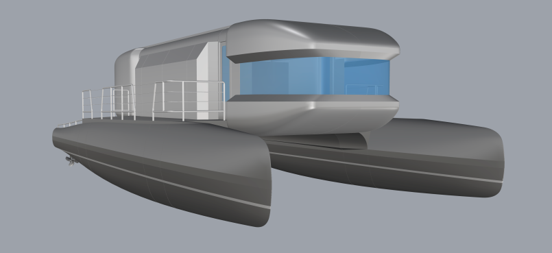
The research ship is currently under construction!