Facilities at EMPI - RF

Research at EMPI is based on various experimental facilities. They are used for the analysis of microscopic details of reaction processes in shock wave apparatus and flow reactors. Spectroscopic properties, energy transfer processes are studied with laser-based methods. Systems for the synthesis of nanoparticles are available from the laboratory scale to pilot-plant production scale. Combustion processes are investigated in laboratory flames and in large systems such as turbulent flames and  in internal combustion engine test cells.

There are numerous laser systems (UV tunable lasers, tunable excimer lasers, high-repetition-rate Nd:YAG laser).

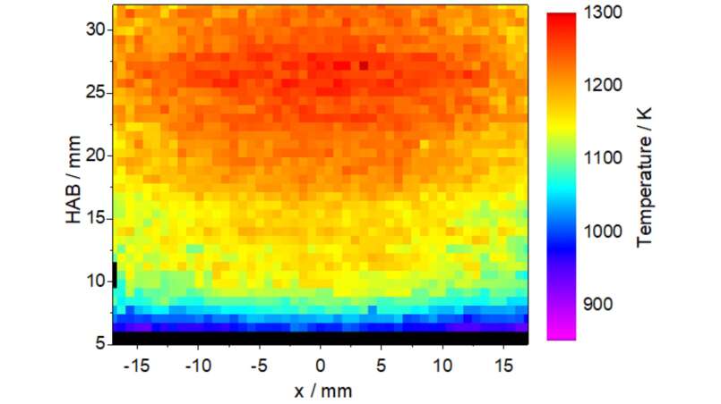
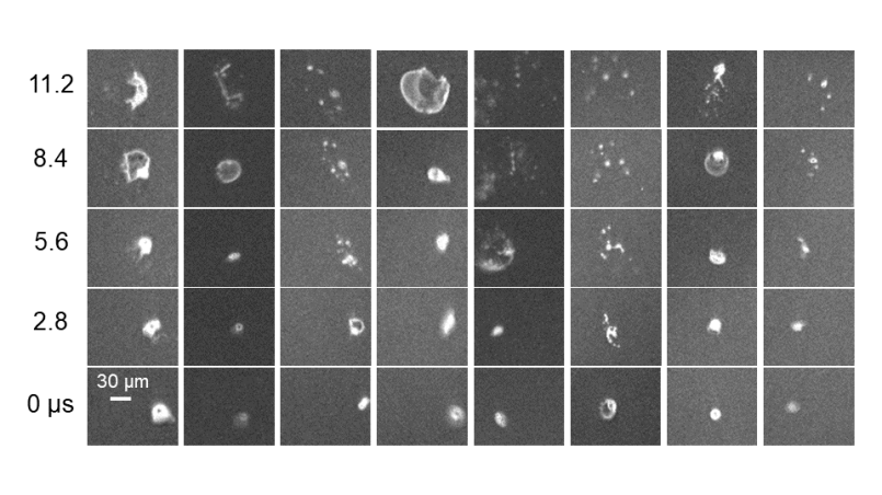
A comprehensive equipment fleet with imaging detectors (EMCCD, ICCD, high-repetition-rate CMOS camera) is used for imaging diagnostics, for example of the in-situ detection of quantitative concentration distributions in reaction processes.

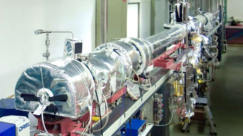
A total of five shock tubes (up to 500 bar peak pressure), equipped with absorption techniques (ARAS, ring-dye laser absorption, kinetic spectrometer and high-repetition-rate mass spectrometry) are used to elucidate the rate of elementary reactions of complex reaction mechanisms.

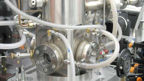
Reaction cells and flow equipment are available from high vacuum to 40 bar

Nanoparticle synthesis facilities

Flame reactor

Aim
Nanoparticles with specific properties are often synthesized in gas-phase processes. They have the advantage of providing material with high purity and high production rates can be achieved in continuous flow systems. The properties of the produced particles depend largely on the conditions during the synthesis. Non-intrusive laser-optical methods enable the observation of these conditions during the synthesis. Gas-phase temperature and species concentrations are of major interest. This information is used for the development and validation of simulation methods that describe the entire synthesis reaction. For these applications, however,  no established measurement approaches are available so far. The facility at IVG allows the development of diagnostics methods for nearly all operating conditions, which can then be transferred to synthesis plants on a larger scale.

Approach
Laser-Induced fluorescence spectroscopy enables the quantification of both temperature and species concentration from based on electronically excited molecular or atomic species with subsequent collection of fluorescence signals. On one hand techniques for the detection of important species are developed, such as atomic species or small molecules (mostly oxides or fragments of the metal organic precursors). On the other hand, the fluorescence spectra often strongly depend on temperature and thus provide an opportunity for measuring local gas-phase temperatures. For temperature measurements, typically small concentrations of nitric oxide (NO) are added to the fresh gases as a measurement target. Based on light sheet techniques, these quantities can be determined in two or even three spatial dimensions. The measured data support the modeling of the process and helps to validate numerical simulation methods.

References
Kronemayer H., Ifeacho P., Hecht C., Dreier T., Wiggers H., Schulz  C. Appl Phys B 88:373-377 (2007)

Hecht C., Kronemayer H., Dreier T., Wiggers H., Schulz C. Appl Phys B 94:119 (2008)

Plasma reactor with pms

Aim
Gasphase synthesis of nanoparticles using high temperature gradients and short residence time can be realized in plasma reactors. They also allow for online and inline diagnostics. The characterization of the synthesized products within the high temperature gradient zone yields information about the involved growth processes and their kinetics. The start of particle formation process is analyzed with a particle mass spectrometer (PMS) that is connected to the reactor. The reactor also allows to produce sufficient amounts of material for further ex-situ characterization methods (TEM, BET, XRD). Furthermore, selected nanoparticles with a selected size can be deposited on unstructured and structured substrates for the characterization of specific material properties.

Approach
The microwave plasma reactor constitutes a microwave source (f = 2.45 GHz) with a maximum power of 2 kW and a 30 mm diameter fused silica tube as the reactor zone. The pressure in the reactor can be varied between 10 and 100 mbar. A large number of precursors are used such as silane, methane and TTIP. With the ability to perform online-analysis using the particle mass spectrometer, the particle size and particle size distribution can be measured in-situ. The reactor is enhanced by gas analytics (MS) and laser diagnostics (NO LIF, atom LIF). Deposition of nanoparticles with a selected size is realized by molecular beam sampling as multi or sub mono layers.

References
J. Knipping, H. Wiggers, B. Rellinghaus, P. Roth, D. Konjhodzic, C. Meier, Synthesis of High Purity Silicon Nanoparticles in a Low Pressure Microwave Reactor, J. Nanosci. Nanotechnol. 4 (2004) 1039-1044

Low pressure flame reactor

Aim
Flame reactors are frequently used for nanoparticle synthesis because they achieve in a straightforward manner high temperatures and large chemical yields. However, in many cases the reaction processes involved are not sufficiently understood. To investigate the chemistry related to combustion and particle formation, a premixed low-pressure flame has several advantages. Due to the mixing of the gases in ad-vance of the combustion process, a homogeneous flame perpendicular to the flow direction can be stabilized. Low pressure expands the reaction zone. Therefore, the flame can be investigated with high spatial resolution. Powerful analyzing tools such as laser spectroscopy and molecular beam sampling with mass-selective detection are combined with the low-pressure flame reactor. As a result, transient species in the flame can be analyzed and the formation and growth of particles can be studied. Furthermore, the molecular beam is also used do deposit size selected particles on substrates.

Approach
The low-pressure flame reactor consists of a water-cooled burner with horizontal flow direction mounted inside a vacuum chamber. It is fed with premixed gases. Hydrogen, acetylene, or propane serve as burner gases, while oxygen is used as an oxidizer and nitrogen or argon as diluents. The operating pressure ranges from 15 to 50 mbar. To investigate particle formation, precursors can be fed into the premixed flame gases directly or – in case of a liquid – by means of a bubbler system. The dis-tance between the burner and a probing nozzle can be adjusted to allow for prob-ing,at different positions, i.e. residence times, with a sampler/skimmer configuration. The resulting molecular beam is analyzed with a particle mass spectrometer (PMS) and a time of flight spectrometer (TOF), respectively. The measurement range is 2–15 nm for the PMS and 1–10,000 amu for the TOF. Additionally, the flame can be investigated via radial mounted optical ports enabling for laser-based techniques like laser-induced fluorescence (LIF) and laser-induced incandescence (LII).

References
P. Ifeacho, T. Huelser, H. Wiggers, C. Schulz, P. Roth, Synthesis of SnO2-x nanopar-ticles tuned between 0 < x < 1 in a premixed low pressure H2/O2/Ar flame, Proc. Combust. Inst. 31 (2007) 1805-1812.

Hot wall reactor 126

Aim
Hot–wall reactors are versatile facilities, which can be used to produce various prod-ucts. They are in particular useful for the formation of nanoscaled materials that are accessible by thermal decomposition of precursors. By controlling the reaction pa-rameters like temperature, pressure, concentration and residence time, particle size and –morphology and therefore the material properties can be changed and adjust-ed. Hot–wall reactors require complex measurement instrumentation techniques for a detailed control and adjustment of the experimental parameters. As many materials that can be produced in hot-wall reactors are sensitive to air, an automatic filling pro-cedure under a protecting gas is necessary. Sufficient availability of highly specific nanomaterials accessible via a hot-wall reactor is important for testing new materials for industrial applications. Hot–wall reactors are designed for continuous production and enable for a high production rate.

Approach
Main part of the hot–wall reactor 126 is a vertically mounted tube furnace with a height of 2.4 m and an inner diameter of 126 mm. The heating zone consists of 6 separately controlled heating units with a total power of 16 KW. The maximum work-ing temperature is 1100°C. The apparatus is designed for a wide pressure range and can be operated between 10 and 1500 mbar. The production rate is between some hundred grams and up to several kg per hour. Back purged filter elements and a ni-trogen purged transfer chamber enable an automatic filling into gas tight bins during synthesis. The facility is equipped with more than 30 sensors for flow, temperature, pressure, and computerized for data logging. To determine the reaction yield, gase-ous components are analyzed periodically with gas–chromatography. Due to its size, a complex safety system is integrated to enable a safe operation during the use of burnable and hazardous gases. The HWR 126 is mainly used to synthesize silicon made from monosilane.

References
H. Wiggers, R. Starke, P. Roth, "Silicon Particle Formation by Pyrolysis of Silane in a Hot Wall Gasphase Reactor", Chem. Eng. Technol. 24, 261-264 (2001).

Hot wall reactor 50

Aim
Hot-wall reactors are suitable for the specific synthesis of non-oxidic nanoparticles from the gas phase. Nanoparticle properties like size, size distribution and morphology can be controlled and tuned by adjusting flow conditions, pressure and temperature. Especially the scientific investigation of nanoparticle formation and growth requires reactors with good accessibility and multiple measurement and sampling possibilities. Online-techniques such as laser-induced incadescence (LII) and almost undisturbed sampling methods deliver valuable information about particle formation and growth under selected conditions. This information is highly conducive to process optimization as well as to the further development and validation of computational fluid dynamics and modeling of particle formation and growth.

Approach
The HWR50 consists of a vertically mounted fused silica hot wall reactor with a subsequent particle filter for the separation of the synthesized nanoparticles. The reactor enables for a parallel as well as a graded feeding of precursor gases. Therefore, not only pure materials but also core/shell materials such as carbon-coated iron nanoparticles are available. The hot wall reactor can be heated up to 1000°C and can be operated between 10 mbar and atmospheric pressure. The reactor provides a couple of optically and mechanically accessible regions downstream the heating zone. Optical measurements such as LII and laser-induced fluorescence (LIF) and nanoparticle extraction can be realized during operation. Synthesis of up to a few gram per hour is possible for ex-situ characterization and post-processing of as-prepared nanomaterials. Particle sampling and filling is possible under inert gas conditions.

References
Orthner, H.R., Roth, P., Materials Chemistry and Physics 78, 453-458 (2002)

Microwave plasma reactor

Aim
Gasphase plasma reactors are particularly suitable for the synthesis of non-aggregated, highly specific nanomaterials, especially based on silicon. Silicon is a basic material in semiconductor industry. It is used in applications like computer chips, photvoltaic cells and sensors. In combination with germanium it is a frequently-discussed material for high-temperature thermoelectrics. Nanostructuring of silicon reveals several new properties of a well-known material, e.g. tunable photoluminescence, enhanced thermoelectric performance and properties that makes it suitable for applications in lithium-ion batteries with increased storage capacity. This reactor enables for the synthesis of tailored, crystalline nanoparticles in quantities that are sufficient for the exploration of their benefits to numerous applications. It also allows to investigate the particle formation process and the influence of synthesis parameters on the particles’ size, morphology and properties.

Approach
The microwave flow reactor generates an argon/hydrogen plasma, which decomposes gaseous precursors, e.g. silane (SiH4) into components, forming a supersaturated vapor. Depending on the conditions during synthesis, this vapor forms solid, crystalline materials with diameters between 5 and 100 nm. Production rates from 0.5 to 10 gram per hour are possible. The resulting product is carried by the gas flow into a strainer and collected by a filter device. It can be bottled under inert gas atmosphere. Surveillance of quantitative conversion from precursor to particles is validated by mass spectrometry. The synthesis takes place at 10 to 200 mbar, a microwave-power between 1 to 2.5 kW and an overall mass flow between 5 to 15 slm, while the precursor flow varies between 10 to 200 sccm.
Plasma-based approaches allow for the synthesis of different oxidic and non-oxidic nanoparticles from gaseous and vaporized precursors.

References
J. Knipping, H. Wiggers, B. Rellinghaus, P. Roth, D. Konjhodzic, C. Meier „Synthesis of high purity Silicon nanoparticles in a low pressure microwave reactor“ J. Nanosci. Nanotech. 4, 1039-1044, (2004).

Analytics

Aim
The physical and chemical characterization of samples from materials science with established methods is an important tool in scientific work. In case of nanomaterials the optical properties are characteristic due to quantum size effects. Optical measurements reveal information about the electronic structure. Additionally, nanomaterials are characterized by a large surface area. A non-destructive method to investigate this feature uses gas adsorption.
Synthesis of nanomaterials in the IVG labs is mostly based on gas-phase processes. The determination of chemical pathways often requires a detailed chemical analysis. For this purpose, a combination of gas chromatography and mass spectrometry (GC/MS) is a powerful tool. It enables to analyze mixtures as well as pure substances. GC/MS allows a quantitative determination.

Approach
The optical properties of materials are characterized by the optical absorption and the fluorescence. In our lab, the former can be measured with a Cary 400 UV-Vis-spectrometer while the fluorescence can be analyzed by means of a FluoroLog FL3 fluorescence spectrometer. High quality spectra are achieved by using double monochromators and a detector equipped with a Peltier cooling. The quantum yield can be determined by means of an integrating sphere. Both devices are also equipped with special sample holders for powders. The gas adsorption is measured with nitrogen at 77 K with a Quantachrome Nova 2200 analyzer. The instrument is equipped with two outgassing and one measuring station. A detailed determination of the adsorption isotherm can be used to receive information about the pore size of the material. For GC/MS measurements an Agilent GC 7890 N attached to a MSD 5975 mass analyzer is available and liquid as well as gaseous samples can be analyzed. For highly sensitive detection of hydrocarbons there is also a flame ionization detector available.

Contact
Dr. H. Orthner, Hans Orthner, Tel.: +49 (0)203 - 379 8030, IVG

Contact

apl. Prof. Dr. H. Wiggers

Chemical kinetics facilities

UHV shock tube 1

Aim
Shock tubes are frequently used to study the kinetics of high temperature gas-phase reactions. A shock wave that is initiated by a gas expansion heats the reactive gas mixture within less than a microsecond to temperatures up to several thousand Kelvin. Subsequent reacting mixtures are investigated by means of optical techniques. Highly sensitive and selective spectroscopic methods provide time-resolved atomic and molecular species concentration measurements and enable the investigation of elementary reactions in highly diluted homogeneous gas mixtures without perturbing side-reactions. Special emphasis is placed on the determination of rate coefficients of unimolecular and bimolecular reactions. The investigations are focused on organic molecules. The experimental data are the basis for the development and validation of reaction mechanisms that can then be used for numerical simulations of combustion systems.

Approach
The shock tube has a total length of 9.2 m an inner diameter of 79 mm. It is divided by an aluminum diaphragm (up to 0.1 mm thickness) into a driver section (3.5 m) and a driven section (5.7 m in length). The reactive gas mixtures are prepared in a stainless-steel mixing vessel. The driver section is filled with H2 until the diaphragm bursts. Pressure sensors measure the shock wave velocities from which the reaction conditions (pressure and temperature) are determined. Time-resolved species concentrations measurements of molecules and atoms are monitored by ring dye laser absorption spectroscopy (RDLAS, UV-VIS) and atomic resonance absorption spectroscopy (ARAS, VUV-UV), respectively. The setup of the shock tube (turbo molecular pump close to the probe volume) favors the applicability of H-ARAS. Both methods enable a selective and sensitive concentration measurement in the ppm range. The kinetics leading to the excited state species (OH*, CH*, C2*) in reactive systems can be investigated by emission measurements.

References
Kathrotia, T.; Fikri, M.; Bozkurt, M.; Hartmann, M.; Riedel, U.; Schulz, C. Combust. Flame 157 (2010) 1261-1273

UHV shock tube 2

Aim
Shock tubes are frequently used to study the kinetics of high temperature gas-phase reactions. A shock wave that is initiated by a gas expansion heats the reactive gas mixture within less than a microsecond to temperatures up to several thousand Kelvin. Subsequent reactions are investigated by optical techniques. Highly sensitive and selective spectroscopic methods provide time-resolved atomic and molecular species concentration measurements and enable the investigation of elementary reactions in highly diluted homogeneous gas mixtures without perturbing side-reactions. Special emphasis is placed on the determination of rate coefficients of unimolecular and bimolecular reactions. The spectrum of the investigated species ranges from simple organic to metal-organic molecules which are applied for nanoparticle synthesis and chemical vapor deposition. The data are the basis source for development and validation of reaction mechanisms that are then used for the numerical simulation of reactive flows.

Approach
The shock tube has a total length of 9.2 m an inner diameter of 79 mm. It is divided by an aluminum diaphragm (up to 0.1 mm thickness) into a driver section (3.5 m) and a driven section (5.7 m in length). The reactive gas mixtures are prepared in a stainless-steel mixing vessel. The driver section is filled with H2 until the diaphragm bursts. Pressure sensors measure the shock wave velocities from which the reaction conditions (pressure and temperature) are determined. Additional to the thermal excitations of reactive species, reactive molecular fragments can also be generated via photo-dissociation initiated by ArF excimer laser radiation. Time-resolved species concentrations measurements of molecules and atoms are monitored by a ring dye laser absorption spectroscopy (RDLAS, UV-VIS) and atomic resonance absorption spectroscopy (ARAS, VUV-UV), respectively. Both methods enable a selective and sensitive concentration measurement in the ppm range.

References
Fikri, M.; Makeich, A.; Rollmann, G.; Schulz, C.; Entel, P. J. Phys. Chem. A  (2008),  112(28),  6330-6337.

High pressure shock tube (HPST)

Aim
Shock tubes are frequently used to study the kinetics of high temperature gas-phase reactions. A shock wave that is initiated by a gas expansion heats the reactive gas mixture within less than a microsecond to temperatures up to several thousand Kelvin. The subsequent reaction is observed via optical techniques. The High-Pressure Shock Tube at IVG allows to study ignition delay times of undiluted fuel/air mixtures that are relevant for the modeling of the behavior of practical fuels for internal combustion engines. Of specific interest is the dependence of ignition delay times on the chemical composition of the fuel. The measured data support the theoretical description of the ignition and combustion chemistry and, thus, the use of new fuels (e.g. bio-derived) and the tailoring of fuel mixtures for specific applications. The study of the ignition behavior of mixtures of gaseous fuels and air are additionally of interest for the development of clean-burning gas turbines and for studying safety issues.

Approach
The shock tube has a total length of 12.5 m an inner diameter of 90 mm. It is divided by an aluminum diaphragm (up to 7 mm thickness) into a driver section of 6.1 m and a driven section of 6.4 m in length. The reactive gas mixtures are prepared in a stainless-steel mixing vessel. The driver section is filled up to 100 bar with He / Ar mixtures until the diaphragm breaks. Adjusting the driver gas mixture allows to realize test times of up to 15 ms. The maximum post-combustion pressure is 500 bar. The driven section and the mixing vessel can be heated electrically up to 250°C to allow the study of low vapor-pressure fuels. Shock wave speeds and ignition are observed via pressure transducers. The flame luminescence is detected with photomultipliers and with CCD cameras through an optional window in the end flange. Gas samples can be taken from the gas and analyzed with a GC/MS (gas chromatograph / mass spectrometer) system in order to investigate potential variations in gas composition prior to ignition. Comparable facilities are available in less than 10 labs worldwide.

References
Herzler, J.; Fikri, M.; Hitzbleck, K.; Starke, R.; Schulz, C.; Roth P.; Kalghatgi, G. T.Combust.Flame2007, 149, 25-31.
Cancino, L. R.; Fikri, M.; Oliveira, A. M. M.; Schulz, C. Proc. Combust. Inst. 2009, 32.

TOF-MS shock tube

Aim
Shock tubes are frequently used to study the kinetics of high temperature gas-phase reactions. A shock wave that is initiated by a gas expansion heats the reactive gas mixture within less than a microsecond to temperatures up to several thousand Kelvin. The subsequent reactions are observed by time resolved time-of-flight mass spectrometry. Thus the TOF/MS shock tube at IVG is well suited for the investigation of reactions which do not offer access by optical techniques. Of specific interest are complex reaction systems, e.g. the formation of nanoparticles from respective precursors. The measured data support the theoretical description and modeling of the particle formation processes. Thus this approach supports the design and synthesis of new materials.

Approach
The shock tube has a total length of 9.0 m an inner diameter of 80 mm. It is divided by an aluminum diaphragm (up to 0.1 mm thickness) into a driver section of 2.75 m and a driven section of 6.25 m in length. The reactive gas mixtures are prepared in a stainless-steel mixing vessel. The driver section is with He or H2 mixtures until the diaphragm breaks. The whole shock tube and the mixing vessel can be heated electrically up to 150°C to allow the study of low vapor-pressure species (e.g. metal-organic particle precursors). Shock wave speeds are observed via pressure transducers. Complex reaction systems can be studied with a high repetition-rate time-of-flight mass spectrometer. Gas samples can be taken from the gas and analyzed with a GC/MS (gas chromatograph / mass spectrometer) system. Comparable facilities are available in only two more labs worldwide.

UV absorption shock tube

Aim
Shock tubes are frequently used to study the kinetics of high temperature gas-phase reactions. A shock wave that is initiated by a gas expansion heats the reactive gas mixture within less than a microsecond to temperatures up to several thousand Kelvin. The subsequent reaction is observed via optical techniques. The UV absorption shock tube at IVG allows for the time- and wavelength-resolved detection of UV spectra of reacting gas mixtures. One application is the investigation of fluorescence tracers at temperatures relevant to practical combustion engines. These species are hydrocarbons which are added to fuels in order to visualize the fuel/air mixing process in real combustion engines by means of stimulated fluorescence. Furthermore numerous reaction systems can be studied provided that the educts or products posses UV absorption bands.

Approach
The shock tube has a total length of 10.9 m an inner diameter of 80 mm. It is divided by an aluminum diaphragm (up to 300 µm thickness) into a driver section of 3.6 m and a driven section of 7.3 m in length. The reactive gas mixtures are prepared in a stainless-steel mixing vessel. The driver section is filled He or H2 until the diaphragm breaks. The maximum post-shock pressure is 10 bar. Shock wave speeds are observed via pressure transducers. A kinetical UV absorption spectrometer (consisting of a spectrometer and an EMCCD-camera) allows for absorption measurements with a high temporal resolution over a broad range of wavelength. Furthermore it is possible to use a photomultiplier to detect chemiluminescence.

Contact

Dr. Mustapha Fikri

Applied Spectroscopy facilities

High pressure cell 1

Aim
For studying gaseous flows, fuel distributions or mixing processes, often a mixture of fluorescence tracers in a non-fluorescing environment is used to visualize the gas flow, e.g., via laser induced fluorescence (LIF). Most tracers show significant dependences of their fluorescence yield on pressure, temperature and gas composition. For an exact analysis of LIF measurements these fluorescence properties of the tracers for defined conditions need to be known. The data gained in the high pressure cell are used on the one hand, for the empirical analysis of measurements and, on the other hand, for developing and refining fluorescence models for predicting fluorescence yields under certain conditions. In this case not only the spectral profile and the intensity of the fluorescence signal is of interest, but also the effective fluorescence lifetime yields important information. Therefore, in our work the measurement of fluorescence lifetimes is of great interest.

Approach
The cell is constructed as a flow cell. It is designed for a pressure range up to 10 bar and a temperature range from room temperature to 1000°C. The cell is internally heated by MoSi heating elements. The gas flow is directed through a ceramic tube system for heating up the flow and then led through the measurement volume. The gas flow is seeded with the respective tracer by an evaporation system. A second gas flow and a gas mixing chamber allow different gas compositions to be realized. A frequency-quadrupled Nd:YAG laser with a pulse length of 30 ps is served as excitation source. This enables fluorescence life times down to about 100 ps to be measured. Three different detection systems are available: A standard ICCD camera with spectrograph (for spectrally resolved measurements), several photomultipliers (for lifetime measurements) and a streak camera with spectrograph.

References
W. Koban, J. D. Koch, R. K. Hanson, and C. Schulz "Toluene LIF at elevated temperatures: Implications for fuel/air ratio measurements," Appl. Phys. B 80, 147-150 (2005).

High pressure cell 2

Aim
For studying gaseous flows, fuel distributions or mixing processes, often a mixture of fluorescence tracers in a non-fluorescing environment is used to visualize the gas flow, e.g., via laser-induced fluorescence (LIF). Most tracers show significant dependence of their fluorescence yield on pressure, temperature and gas composition. For quantitative analysis of LIF measurements these fluorescence properties of the tracers for defined conditions need to be known. The fluorescence properties of standard fuels – which often fluoresce following excitation by uv-laser radiation – are also of great interest. With this information it is possible to optimize combustions processes and to minimize pollutants using these novel laser-diagnostics approaches.

Approach
Regulated mass flows of the relevant gases are introduced into the cell in a flow configuration. The cell is designed for a pressure range up to 40 bar and a temperature range from room temperature to 550°C and is equipped with four quartz windows. The cell is located inside an oven to ensure a homogenous temperature distribution. The gas flow is mixed with a small, well controlled flow of the respective vaporized tracer using an evaporation system. A second gas flow and a gas mixing chamber allow different gas compositions to be delivered. The substances are optically excited by radiation from excimer lasers or frequency-converted Nd:YAG laser beams. As detection system an ICCD camera with spectrograph is available. For fluorescence lifetime measurements via time-correlated single photon counting (TCSPC) a high repetition rate short-pulse laser and a fiber sensor can be mounted after minor modifications of the setup.

References
F. Zimmermann, W. Koban, C. M. Roth, D.-P. Herten, and C. Schulz "Fluorescence lifetime of gas-phase toluene at elevated temperatures," Chem.  Phys. Lett. 426, 248-251 (2006).

Counterflow diffusion flame

Aim
For safety reasons diffusion flames – where fuel and air are introduced separately into the combustion chamber and form an ignitable mixture by diffusion – are widely used in practical combustion systems. Additionally, measurements in diffusion flames provide valuable data with respect to optimizing combustion processes and experimental data for validation of flame modelling.

We perform optical diagnostic measurements within diffusion flames at atmospheric pressure where fuel and air impinge on each other in a counterflow geometry. Aa laminar flame can be stabilized in the stagnation region of both gas flows in an optically accessible combustion chamber of rectangular cross section. Using laser-spectroscopic techniques and conventional emission spectroscopy spatially resolved temperatures concentration values of minority species as well as spectrally resolved chemiluminescence within these flames can be determined.

Approach
The burner consists of a 1 m long air flow channel with a converging nozzle on which the combustion chamber is attached (internal squared cross section of 10 × 10 cm2). Four fans at the bottom of the channel deliver an air flow with a top hat velocity profile in the optically accessible combustion chamber where it hits the fuel flow emanating through a 1 cm wide sinter plate as part of a cylindrically shaped burner head. The water cooled burner head can be translated in vertical direction using a motor driven translation stage. Fuel (CH4, H2) and an additional coflow (N2) are metered with mass flow controllers.

Temperatures are determined by fitting simulated to measured NO laser-induced fluorescence (LIF) excitation spectra of NO, which is added to the air flow in small amounts (100–500 ppm). Fluorescence is detected with intensified CCD cameras. Formaldehyde and OH radicals are also detected using LIF, while spatially resolved chemiluminescence spectra are obtained with a spectrograph/CCD camera setup.

High pressure burner

Aim
High-pressure combustion reactions are common in practical applications like internal combustion engines, gas turbines in power plants or jet-propulsion engines. Due to the fact that these systems are highly complex and in case of the combustion in engines they are even unsteady, it is difficult to study fundamental processes. in a premixed burner, a steady high pressure flame provides the possibility to specifically address certain conditions while all the other parameters stay constant. The mean research topic at this facility is the study of soot formation as a function of the pressure in high pressure flames and to study the influence on pressure on soot measurement techniques, such as laser-induced incandescence (LII). For this, additional measurements based on absorption spectroscopy or angle-resolved scattering are possible. The burner is designed for operating pressures up to 40 bar.

Approach
The high-pressure burner consists of three concentric porous metal plates that feed gas mixtures of different composition into the burner housing. The inner burner (supplied with C2H4+ air, rich, premixed) generates the sooting flame of interest. It is surrounded by a burner (supplied with CH4 + air, stoichiometric, premixed) to stabilize the inner flame with minimal thermodynamic, reactive or optical influence. Around the surrounding flame a flow of air shields the hot combustion gases from the walls and the windows. Optical access is provided via four windows (at 90° to each other) at the side of the burner. Soot particles are heated to incandescent temperatures by a pulsed Nd:YAG laser (1064 nm). The detection of the incandescence takes place via fast photomultipliers (rise time 0.8 ns) at two different wavelengths, which gives also the possibility to determine the temperatures of the laser-heated soot particles via two-color pyrometry. From the variation in light emission during the cooling period of the laser-heated particles information about particle sizes is gained.

References
M. Hofmann, W. G. Bessler, C. Schulz, H. Jander, "Laser-induced incandescence (LII) for soot diagnostics at high pressure," Appl. Opt. 42, 2052-2062 (2003)

Test facility turbulent flame

Aim
Turbulent gas flames are of high practical importance. This test facility is used for the investigation of reaction processes in turbulent premixed and non-premixed methane flames at atmospheric pressure. For that purpose qualitative and quantitative instantaneous species concentration distributions of combustion-related species and temperature are determined with laser-based methods. Additionally, the luminescence of electronically excited molecules (chemiluminescence) in the flame is observed. The measurements provide input for the modeling of turbulent reactive flows. They also allow to further develop the quantitative understanding of chemiluminescence that can be detected from turbulent flames. This is of interest for making the simple chemiluminescence detection a quantitative tool for flame studies and for control systems in industrial applications. The aim of this work is to further develop laser-based methods and to contribute to the development of chemiluminescence sensors.

Approach
In the facility a 30 kW swirl burner is used, which has a moveable-block design to adjust the swirl number and thus, turbulence. The burner has a circular nozzle with a bluff-body in the center to provide flame stabilization. It can be operated either with premixed, or non-premixed gases. The visualization of species distributions in the flame is carried out by detection of laser-induced fluorescence (LIF), using intensified CCD-cameras and 2D uv-laser-lightsheet techniques. Temperature information can be obtained from the detection of Rayleigh scattering. The distribution of heat-release is determined based on an approach that combines measured OH- and CH2O-LIF intensities. In order to investigate correlations between LIF and chemiluminescence signals, additionally spectrally resolved chemiluminescence is detected with optical sensors in combination with optical filters or spectrometers.

References
Böckle, S.; Kazenwadel J.; Kunzelmann, T.; Shin, D.-I.; Schulz, C.; Wolfrum, J. Proc. Combust. Inst. 28, 279-286 (2000) | Böckle, S.; Kazenwadel, J.; Kunzelmann, T.; Schulz, C. Appl. Phys. B 71, 741-746 (2000).


Kontakt

Dr. Torsten Endres

Imaging facilities

Optically accessible engine

Aim
The development of modern internal combustion engines requires the observation on in cylinder processes. Laser diagnostics methods allow for the observation of fluid flow fields, fuel/air mixture formation, ignition and pollutant formation. The IVG single cylinder engine is fully optically accessible through a quartz ring replacing the upper part of the cylinder liner and a large scale sapphire window in the piston. Therefore, the combustion chamber can be observed from multiple directions and accessed with laser beams. In combination with the versatile laser equipment located in the neighboring laboratory and a number of intensified scientific cameras the facility can be used to develop laser diagnostics methods, to contribute to the development of engine combustion strategies and to provide measured data for the validation of numerical simulations. A comparable combination of laser diagnostics capabilities and the equipment available in the optical engine facility is only available in few labs worldwide.

Approach
The revolution speed of the optically- accessible single cylinder engine (bore: 84 mm) is controlled by a dynamometer (up to 3000 rpm). It is currently set up as an spark-ignition engine with direct injection. Fuel can also be supplied via port-fuel injection. Depending on the application piston and cylinder head can be exchanged for different geometries. The facility is fully equipped with standard engine measurement technology and data logging. It features exhaust gas analytics and fast gas sampling from the combustion chamber. Oil and water temperature is electrically controlled. A wide variety of laser sources (Excimer, Nd:YAG-, dye, high-repetition-rate laser) is available from the neighboring air conditioned laser lab through ports in the wall of the engine test cell. A hydraulically controlled stage holds the quartz ring that provides optical access to the combustion chamber. The window can be removed within minutes to allow for easy cleaning. The engine is operated from a neighboring control room.

References
C. Schulz "Advanced laser imaging diagnostics in combustion," Z. Phys. Chem. 219, 509-554 (2005).

Engine test bench with fourstroke spark ignition engine brake

Aim
Teaching in the framework of the Internal Combustion Engine (ICE) lecture includes laboratory training at an engine test bench with a four-stroke spark ignition engine. in this hands-on project the behavior of an ICE is investigated and mapped in an engine performance map. The energy balance is drawn for different engine loads for the whole range of operating conditions. This is done by varying torque and rotary speed and measuring the fuel consumption. From these data all necessary characteristic parameters like mean effective pressure pme and specific fuel consumption be can be calculated. The engine performance map is limited by several parameters. The range of speeds is restricted by minimum nmin and maximum nmax number of revolutions. The upper limit of engine power is given by the full load curve. For a complete energy balance the measurement of all power losses is necessary and done by measuring the temperature differences between entry and exit and the corresponding mass flows of cooling water, fuel/air mixture and exhaust gas. The concentrations of exhaust gas species are monitored as well.

Approach
The engine test bed is equipped with an eddy current brake which is able to handle engines with a maximum power of 50 kW and a maximum speed of 12,000 revolutions per minute alternatively on both sides of the brake flanges. The test bed is equipped with a 340 liter air vessel for minimizing fluctuations in the intake air flow rate which is measured with a hot film anemometer. The fuel consumption is measured by a continuous volumetric counter. Exhaust gas components like CO, CO2, NOx are detected by NDIR and residual hydrocarbons are measured by a FID. In case of Diesel engines the determination of the Bosch smoke number is possible.

Engine test bench with 220 kW

Aim
Testing the operating behavior of internal combustion engines is the common purpose of engine test stands. Various parameters like fuel consumption or exhaust gas behavior were generally measured as a function of torque and rotary speed and mapped in an engine performance map. One of the main focuses in the research work of the IVG, optical measurements in combustion systems, is systematically applied for in-cylinder investigations of the combustion process. Due to the application of an asynchronous machine as a brake it is possible to apply different test procedures. This enables us to run internal combustion engines under realistic conditions and examine new combustion processes under part and full load conditions and various rotation speeds. The engine test stand is used in research projects that contribute to the further development in the technology of internal combustion engines. The support of the research programs is either related to governmental or industrial funding.

Approach
The engine test stand is equipped with a four-quadrant dynamometer brake which is able to handle engines with a maximum power of 220 kW and a maximum speed of 9,800 rpm.  The engine control is realized by  test bed automation, data acquisition is realized by an indication system using industry standard devices. The test cell is connected to the adjacent laser laboratory via optical ports in the walls. This enables the application of comprehensive laser measuring techniques for internal diagnostics in combustion engines with optical access. Additional equipments are an air vessel with a volume of 400 liters for minimizing fluctuations in the intake air flow which is measured with a hot film anemometer. The fuel consumption is measured by balancing the fuel mass or by a continuous volumetric counter. Exhaust gas components like CO, CO2, NOx are detected by NDIR and residual hydrocarbons are measured by a FID. For soot measurements, Bosch smoke numbers, mobility particle sizers, particle counters, and laser-induced incandescence equipment is available.

Contact

Prof. Dr. Sebastian Kaiser