Startseite


Willkommen auf der Internetpräsenz des INAM!
Das Institut für Nachhaltige und Autonome Maritime Systeme (INAM) ist aus dem Institut für
Schiffstechnik, Meerestechnik und Transportsysteme (ISMT) hervorgegangen.
Wir freuen uns sehr über Ihr Interesse!
Forschung
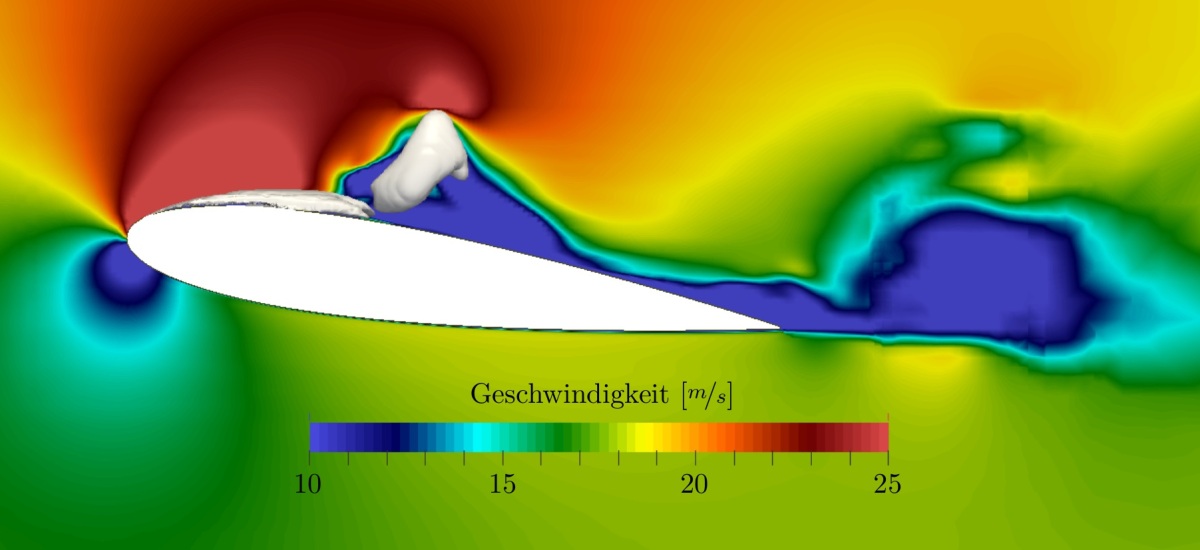
Das Institut für Nachhaltige und Autonome Maritime Systeme (INAM) befasst sich schon seit Jahrzehnten mit der Entwicklung maritimer Systeme auf verschiedenen Skalen, sowohl in der Grundlagen- als auch der angewandten Forschung. Hier spielt das Thema Nachhaltigkeit eine zentrale Rolle, da wir mit unseren Entwicklungen anstreben, den Energiebedarf maritimer Systeme zu reduzieren oder die Leistungsfähigkeit der Systeme bei gleichem Energiebedarf zu erhöhen. Außerdem bearbeiten wir eine Reihe von Projekten, die sich mit der Automatisierung der Schifffahrt befassen. Auch Themengebiete, die sich mit der Aerodynamik von Luftfahrzeugen befassen, sind Gegenstand der Forschung am INAM. Bei allen Forschungsaktivitäten streben wir einen zügigen Transfer der Forschungserkenntnisse in die Ausbildung unserer Studierenden sowie in die maritime Wirtschaft an.
Forschungsschwerpunkte
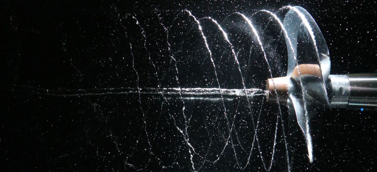
- Kavitation und Mehrphasenströmungen
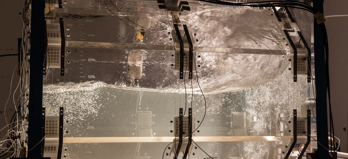
- Wellen- Struktur- Wechselwirkung
- Nachhaltige Maritime Systeme
- Autonome Maritime Systeme
Studium
In Nordrhein-Westfalen und speziell im Ruhrgebiet sind zahlreiche Unternehmen der Offshore-Windenergie angesiedelt. Dadurch wird ein beträchtlicher Teil des Umsatzes der Wind-Offshore-Branche in Nordrhein-Westfalen erwirtschaftet. Zudem ist in Duisburg der größte Binnenhafen Europas und damit einer der wichtigsten Logistikstandorte Deutschlands angesiedelt.
Die Universität Duisburg-Essen (UDE) ist mit dem vielseitigen und anspruchsvollen Studium des Maschinenbaus mit dem Schwerpunkt Nachhaltige und Autonome Maritime Systeme ein optimaler Ort, um sich auf das Berufsleben vorzubereiten. Die neu gestaltete Vertiefungsrichtung stellt moderne Verfahren, die zur Entwicklung nachhaltiger und zukunftsweisender Technologien benötigt werden, in den Vordergrund. Dazu gehören Fächer wie „Regenerative Energiesysteme“ oder „Entwurf Nachhaltiger und Autonomer Maritimer Systeme“. Der Themenkomplex Maschinelles Lernen und Künstliche Intelligenz ist ebenfalls Bestandteil der Ausbildung.
Institutsleitung:
Dr.-Ing. Jens Neugebauer
E-Mail: jens.neugebauer[at]uni-due.de
Raum BK 118, Tel. +49 203 379-1168
_________________________________________________________________________________
Professoren:
Prof. i.R. Dr.-Ing. Milovan Perić
Prof. Dr.-Ing. habil. Tao Jiang (Honorarprofessor)
_________________________________________________________________________________
Sekretariat:
Martina van Lück
E-Mail: Martina van Lück
Mo - Fr: 8:30 - 12:30 Uhr
Raum BK 117
Tel. +49 203 379-1173