Ham Radio
Ham Radio Stations
-
Club and Contest Station DF 0 UD
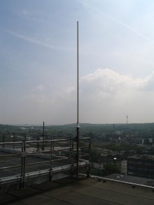
The HFT departement operates the club and contest station DFOUD on the roof of building BB (12th storey) at a height of 55m with activities in Shortwave (SW), VHF and Microwave Bands.

View of Building BB
-
SHF-Beacon DB 0 GW in Duisburg
Call sign: DB 0 GW Location:
JO 31 JK
51° 25' 36'' Nord
6° 47' 24'' OstHeight above S.L: 55m Modulation: A 1 A Send out:
Call sign, Location, Frequency
2 Minutes CWFrequency precision:
(DCF77 synchronised)Long time stabilised: 1 E-13 / h
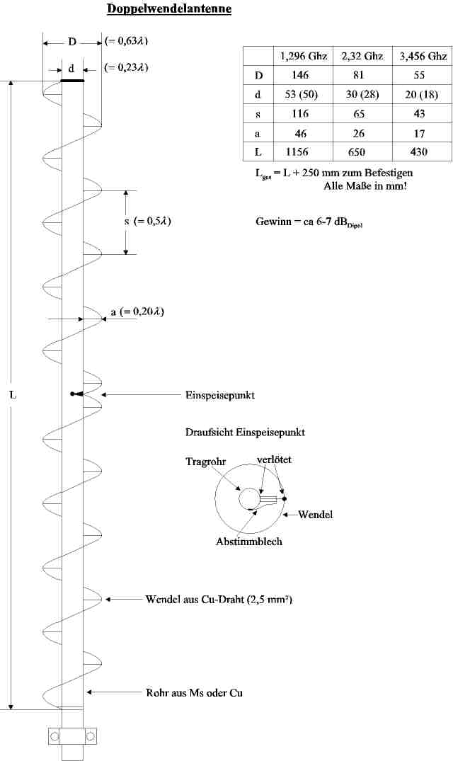
Short time stabilised: 2 E-9 / hFrequency: 2320.85 MHz 3400.85 MHz 1296.95 MHz 5760.85 MHz 10368.85 MHz 24048.85 MHz Output Power: 100 mW 50 mW 100 mW 100 mW 100 mW 50 mW Antenna: Double Helix antenna, horizontally polarised, omni-directional Waveguide Slot Antenna with 2 times 8 Slots, horizontally polarised, omni-directional Gain: approx. 7 dBD approx. 9 dBD 
Double Helix Antenna for 2.3 GHz und 3.4 GHz
-
Repeater Radio Station DB 0 DR
Since 1991 our department operates an amateur radio transmitter station for the 70 cm band, which was built by radio amateurs, members of the staff and students. The automatic transmitter station serves mobil and portable radio stations to communicate with each other intra-city. The transmitter signal is frequency modulated and radiates through a vertical polarized omnidirectional antenna at the top of our building BB.
Antenna for the 70 cm band repeater Specification of the Repeater Radio Station Output Power Level: P = 10 W Location: Building BB of Area Bismarckstrasse 81 (55 m over Ground) Range: approx. 30 km Output Frequency: 439,35 MHz Input Frequency: 431,75 MHz -
Waveguide Slot Antenna with Horizontal Polarization and Omnidirectional Pattern
Vertically installed omni-directional Antennas are developed for the operation of the beacon and the ATV-relais in the range of cm-wavelength on the basis of rectangular waveguides with arrays of slot radiators in one or both broad walls. A QBasic code was developed for the design and dimensioning of antennas. You can download the latest version HLSSA54.bas. It includes comments and references to publications on the basic design data in UKW-reports 1/91 (S. 50-55) und 2/91 (S. 71-77) as well as the IEEE Antennas Propagation Magazine december 1991 (Vol. 33, No. 6, pp. 45-47).
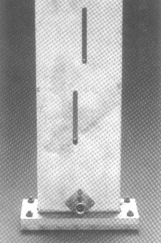
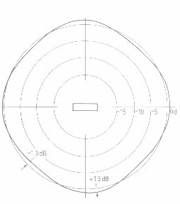
Photo of a 13-cm-Antenna with
9 Slotted-PairsMeasured Omnidirectional Radiation Pattern
of a 23-cm-Antenna with 12 Pairs of Slots
-
Inverted-V Wire Yagi Array with Switched Beam Rotation for Frequency f=14MHz
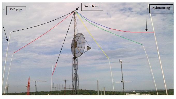
Inverted-V wire switched beam array antenna on the roof platform.
For better visibility, the dipole wires have been colored.
The antenna utilizes six wires sloping under 30° elevation angle from the top of the roof platform tower in 7 meter height. Using a switch unit, two wires are selected for the active dipole and are connected to the feed cable; two wires are selected as parasitic elements and are connected to a capacitor as reactive load. The remaining two wires are left idle.By cyclic interchange of the selected wires, we create six different combinations with radiation patterns separated by 60° in azimuth and covering 0 - 360° of pattern rotation.
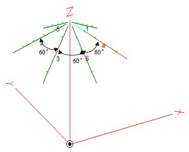
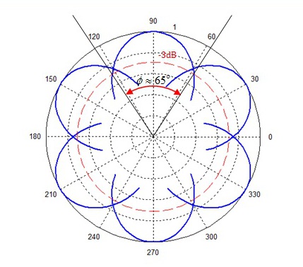
Six wire arrangement of the switched beam array. Sketch of principal patterns created by six selections of wires. The switch unit employs signal relays on a printed circuit board and the relays are remotely controlled by the operator using a digital circuit board with a 6-position rotary switch: Changing beam pointing direction is practically without inertia.
The antenna was realized by our student, Ashraf Abuelhaija, as part of his Master thesis in 2010.
His thesis is available on request as a PDF document from the department.
A paper with detailed information on the design and performance was published in QST, December 2011, pp 34-37!. -
Magnetic Loop Antenna“ – an electrically small HF antenna for transmit and receive.
When there is no space for HF antennas of half-wave length, the capacitively tuned resonant “magnetic” loop antenna (MLA) is a useful alternative. In a DIY project, an MLA for the 40 meter band (7 MHz) was designed, built, tested and analysed. The report (MLA paper, English version) discusses some widely misunderstood RF engineering terms and concepts in connection with the antenna. The misconceptions of several RF terms and concepts are discussed in a further paper (MLA Misconceptions). Another paper presents a matching circuit for improving the impedance match of MLAs (MLA Inpedance Matching). The paper (MLA Frequency Extension) describes how we can add a new frequency band to an existing MLA by inserting an additional loop.
-
Some Dipole Antennas
Although dipole antennas have been known since Heinrich Hertz’ experiments, there is still room for new proposals of innovative or just practical realizations. In this section, a number of practical realizations of short-wave and VHF / UHF dipole antennas are presented. In each proposal, some interesting new aspects of design, simulation and operation are discussed. In Short Dipole for 28 MHz a shortened half-lambda dipole is designed. Derived from this, a light-weight two-band dipole for the 2- and 10-meter bands is presented in "28MHz_145MHz_Rotary_Dipole" and a short rotary dipole for the 10- and 15-meter band is presented in "A Short Portable Rotary-Dipole for 10- and 15-Meter Bands". In Vertical 2 x 5/8 lambda dipole for the 2-meter band, a dipole for the 2-meter band is designed which employs a length of 5/8 lambda to increase the gain. In Lightweight 2m/70cm dipole with increased gain at 70cm, a design is presented which employs the 5/8 lambda dipole for the 70-cm band and at the same time operates as half-lambda dipole at the 2-meter band. A very special antenna for radio amateur operation from a campsite is described in: "Operation from a Motor Home: Antenna for 40 - 10 Meter".
-
Digital Communication Modes
In amateur radio communications, digital modulation has been used for a long time apart from analog modes, like telegraphy (Morse code), Amplitude Modulation and Single Sideband modulation. Presently, the FT4 and FT8 – modes have gained enormous popularity as these modes allow transcontinental communication via short-wave with lowest transmit power and / or using antennas of low efficiency, like Magnetic Loop and even in-room compromise antennas. However, the data exchanged by these modes, apart from the call signs and locations are not directly related to properties of the radio stations, like transmit power and antenna gain. In "FT8 Reports - What we can learn from", the basic radio communication process is reviewed and the particular properties of short-wave propagation. It is shown that based on some reasonable assumptions, a large number of transmit/receive reports from successful exchanges can be evaluated statistically to extract interesting information.
While the digital signal processing of FT8/FT4 communications is done on a computer using the WSJT-X code, the RF part is usually realized in a complex SSB transceiver. However, much simpler RF realizations can be based on a clever concept described in the following two reports: FT8_and_WSPR_using_Si5351_and_Arduino, FT8_Operation_using_Arduino_and_Rockmite_QRP.
When operating FT8/FT4 sometimes the receiver and the WSJT-signal processing generate reports which seem to contradict own expectations concerning S/N-reports on the basis of S-meter indications. This problem was probed experimentally by measuremts and reported in "WSJT put to the test".
A very special transmission mode, the Weak Signal Propagation Reporter (WSPR) - mode produces automatic reception reports from a large number of receiving stations around the world. These can be used to evaluate the present status of ionospheric propagation in the used frequency band. In "WSPR for Antenna Comparison" it is shown how the reception reports for transmissions from two separate Antennas are compared to evaluate which antenna performs better .
-
Parasitic Elements in Inductors, capacitors and resistors
It is widely known that even passive circuit elements can only be used to certain frequency limits. Such limits can be investigated by measurement, and best suited for this is a Vector Network Analyzer. Inexpensive VNA models are on the market and many radio amateurs have acquired one. In a three-part contribution, it is demonstrated how to analyze and understand the frequency limits of coils, capacitors and resistors: Measuring and Understanding RF Coils using the VNA.
-
RF Measurements
After the "wanted" information carrying signals, in RF communications the most important signal is "Noise". In our receivers we can hear noise signals but we also can see noise signals and measure noise signal power, as described in the following short reports: Measure_Noise_Power_by S-Meter, Narrowband_Noise.
Many RF tests require either probing a high-power signal or separating foreward and reflected waves on a transmission line. This is where we can employ a dierectional coupler as in " SWR-meter becomes Directional Coupler".
One such test is measuring the output impedance of a power amplifier,
as described in "The output impedance of HF Power Amplifiers: Not as expected".There are misconceptions around in radio ham circles concerning the behaviour of a Power Amplifier under mismatched load conditions. In the two-part paper "What a PA of a modern transceiver does in case of load mismatch" and "What a PA of a modern transceiver does in case of load mismatch-Part 2" we try to show by measurements what happens in a real power amplifier.
-
Power Amplifiers
Power amplifiers for a few Watt RF output from a few MHz into the VHF range can be extremely simple in design, in particular without using an impedance matching circuit at the Output stage. The paper "A QRP PA for HF from an inexpensive amplifier module" investigates one such amplifier module and shows how to extend the range of generated power by simple modifications.
-
Hamnet
HAMNET is a special wireless LAN for radio amateurs. It uses frequencies on 2,3GHz and 5GHz bands.Information:
User access (13cm) 2397MHz User access (6cm) 5695MHz Link to (in use) DF0MHR (Mülheim a.d.Ruhr)
DB0OHL (Gelsenkirchen Scholven)
DB0HSN (Krefeld)
DB0DUS (Düsseldorf)Projected Link DB0LNR (Schaephuysen)
For more information about hamnet visit this link(Information in german language)
Amateur Radio Links
- German Amateur Radio Club, Homepage
- Funkamateur, periodicals
- Hamradio, Classified advertisements, News, Downloads
- Software Downloads
- ARRL, Homepage of the American Amateur Radio association
- Funkbörse, Advertisements, Online-Auctions
Responsible / Contact
Please contact Prof. Klaus Solbach.