

Our Equipment
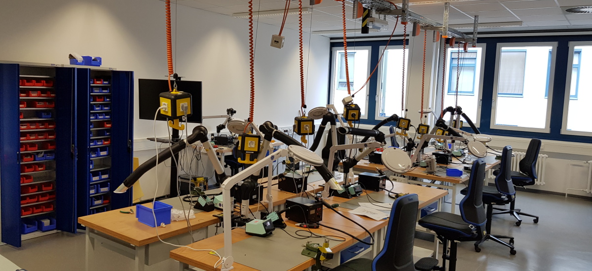
Equipment
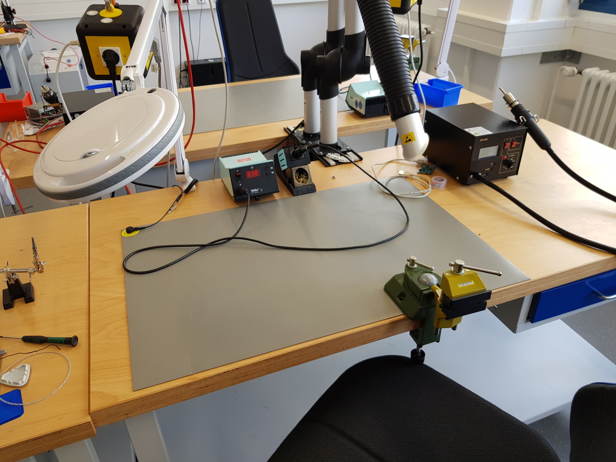
Soldering workstation
With everything that is needed. For the assembly of electronic components with through-hole technology (THT) and surface-mount-device (SMD) technology.

Filament Printer
For the production of mechanical components or housings. We use PLA filament as our standard material for printing.

Resin Printer
For the production of mechanical components or housings. Stereolithography (SLA) can be used to produce highly detailed 3D objects.
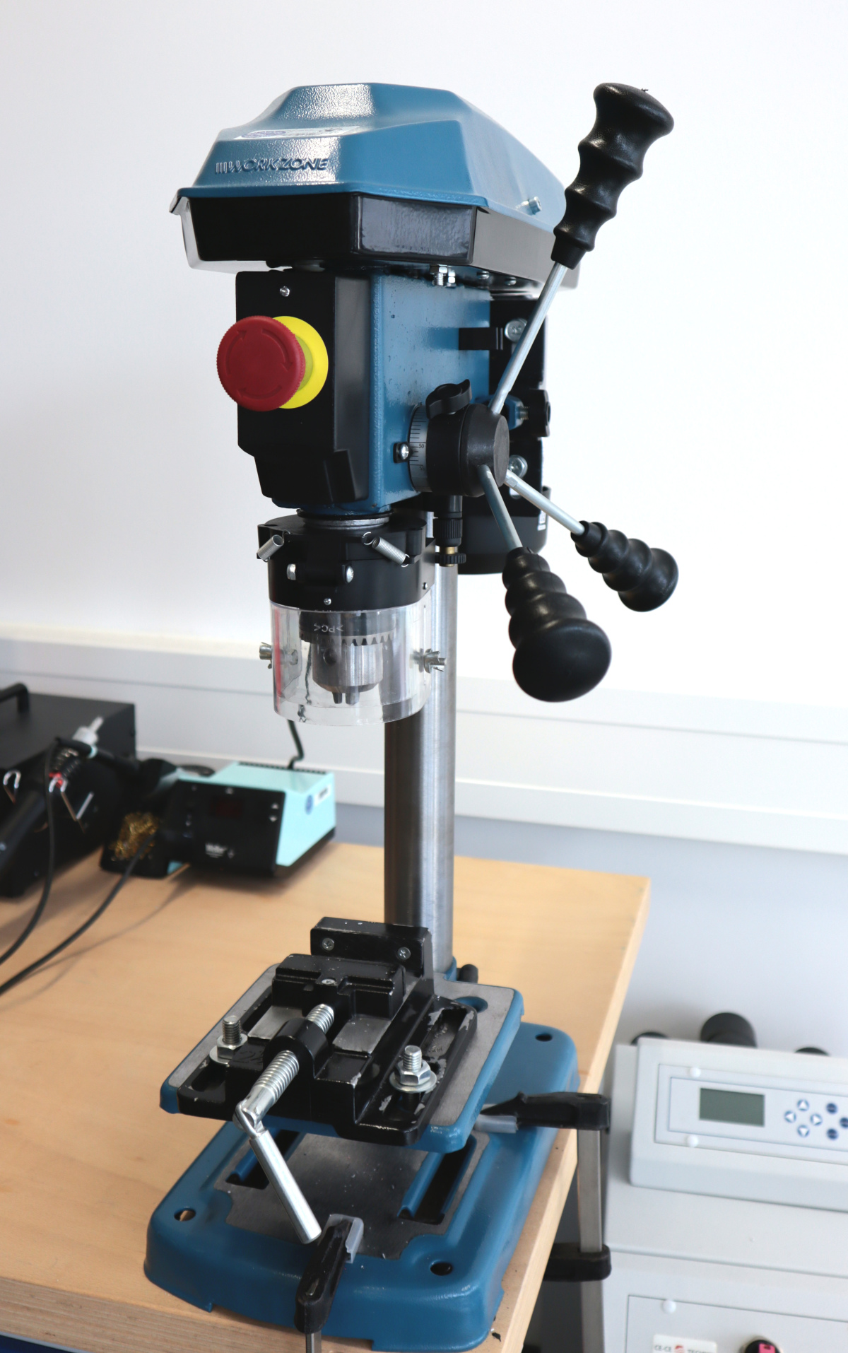
Bench drill
For drilling holes in various materials.
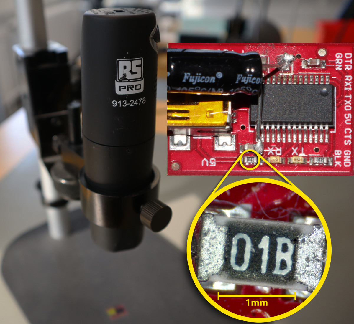
Webcam-Microscope
For inspecting solder joints and other fine work.
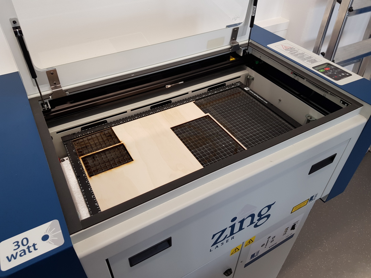
Laser cutter
For the manufacturing of stencils, mechanical components or housings (in layered assembly) from various materials such as wood or acrylic.

Oscilloscopes
For testing circuits and measuring as well as displaying signals.
You can find detailed technical information such as print dimensions or available filaments in the Moodle course.
Our 3D-Resin-Printing Production Line
3D Resin Printer
Step 1: Choose a design and start the 3D print.

TPM Washing System
Step 2: After printing, the TPM washing system is used to wash away any resin residue.

Isopropanol Washing Station
Step 3: The oily film left behind by the TPM washing system is washed off in the isopropanol washing system.

UV Curing Station
Step 4: Once the print has been cleaned, it is cured in the UV curing station using UV light and heat.

Finished Resin-Print
Step 5: Now we have the finished, cleaned, and cured 3D resin print.
Our PCB Production Line
Manufacturing of a 2-layer PCB

PCB Maker
Step 1: In the PCB Maker, the contact holes (vias) are laser-drilled.

Electroplating Bath
Step 2: The PCB is then placed in an electroplating bath, where the holes are plated through to establish an electrical connection between the two copper layers.
Step 3: Back in the PCB Maker, the traces on both sides of the PCB are structured using a laser. At the same time, the PCB is already almost completely cut out. After visual a inspection for possible defects, the green solder mask is applied to protect the PCB against corrosion. Finally, the pads are exposed using the laser in the PCB Maker.
Manufacturing of a multi-layer PCB
PCB Maker
Step 1: In the PCB Maker, the contact holes (vias) are laser-drilled.

MultiLayer PCB Press
Step 2: In the Multilayer PCB Press, the inner layers are laminated together, forming a multilayer board from several individual layers.
PCB Maker
Step 3: In the PCB Maker, the outer layers are manufactured and drilled.
Electroplating Bath
Step 4: The PCB is then placed in an electroplating bath, where the holes are plated through to establish an electrical connection between the two copper layers.
PCB Maker
Step 5: Back in the PCB Maker, the traces on both sides of the PCB are structured using a laser. At the same time, the PCB is already almost completely cut out. After visual a inspection for possible defects, the green solder mask is applied to protect the PCB against corrosion. Finally, the pads are exposed using the laser in the PCB Maker.
PCB assembly

Stencil Printer
Step 1: A stencil is used to mask all areas that should not receive solder paste, after which the solder paste is applied.

Automatic Pick-and-Place Machine
Step 2: An automatic pick-and-place machine is used to place components that are required in large quantities and are readily available.

Manuel Pick-and-Place Machine
Step 3: A manual pick-and-place machine is used to place components that are available only in small quantities (such as Ball Grid Array components or microcontrollers).
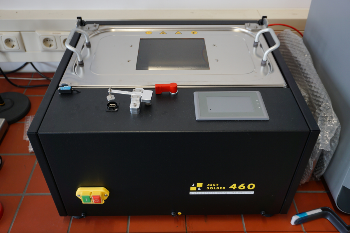
Vapor Phase
Step 4: The PCB is then placed in a vapor phase soldering system to melt the solder and permanently attach the components.

Microscope
Step 5: The assembly can be inspected under a microscope (optionally after each step).